Control components - counters
Self-powered Totalizer
New H7E
Compact Economical Totalizer with High Visibility
Available with Backlit LCD Display
• Large display with 8.6-mm character height.
• Includes new models with backlight for improved visibility in dimly lit places. (Requires 24-VDC power supply.)
• Black and light-gray cases now available.
• PNP/NPN universal DC voltage input types now available.
• Battery is replaceable for Totalizer reuse and conservation of the environment.
• Key-protect switch to prevent faulty reset key operation.
• Dual operation mode.
• Front face compatible with NEMA4/IP66.
• Short body, all models have a depth of 48.5 mm.
• Finger protection terminal block conforms to VDE0106, Part100.
• Conforms to UL, CSA, and CE marking.
Conforms to EN61010-1 (pollution degree 2/overvoltage category III.)
• Conforms to EMC standards and EN61326, thus allowing use in residential, commercial and light- and heavy-industry environ-
• Six-language instruction manual provided.
• PCB-mounting models available. (Requires 3-V power supply.)
■
Broad Line-up of the New H7E Series
Time Counter
• Total Counter (8-digit)
• 1,000 s-1 with
• Time Counter (999999.9h)
1 pulse/rev. encoder
• 999h59min59s/
• 1,000.0 s-1 with
10 pulse/rev. encoder
• 1,000 min-1 with 60 pulse/rev. encoder
• 10,000 min-1 with 60 pulse/rev. encoder
• 1,000.0 min-1 with 600 pulse/rev. encoder
Common to All Totalizers
Accessories .
Precautions .
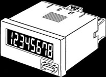
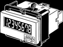
Self-powered Total Counter
New H7EC
• Eight-digits, counting range 0 to 99999999.
• Dual input speed: 30 Hz ←→ 1 kHz (except for AC/DC multi-
voltage input models)
Model Number Structure
■
Model Number Legend
Note: Some configurations are not available.
1. Count Input
3. Display
None: No-voltage input
without backlight
V: PNP/NPN universal DC voltage input
multi-voltage input
2. Case Color
Note: Estimates can be provided for coatings and other specifications that are not given in the datasheet. Ask your OMRON representative for details.
■
Total Counters
Count input
Max. counting speed
Black body
PNP/NPN universal DC
30 Hz ←→ 1 kHz
7-segment LCD with
AC/DC multi-voltage input 20 Hz
(24 to 240 VAC/VDC)
30 Hz ←→ 1 kHz
■
Accessories (Order Separately)
Compact Flush Mounting Bracket
Flush Mounting Bracket (See note 1)
Wire-wrap Terminal (set of two Terminals)
Lithium Battery (See note 2)
Waterproof Packing (See note 1)
Note: 1. Provided with H7EC. (Order additional Brackets separately as required.)
2. Built into H7EC. Order replacements using the above model number before the service life expires.
■
General
Screw terminals, optional Wire-wrap Terminals (see note 1)
External/Manual reset
Number of digits
Count input
PNP/NPN universal DC voltage in- AC/DC multi-voltage input
7-segment LCD with or without backlight, zero suppression (character height: 8.6 mm) (see note 2)
Max. counting speed
Case color
Light gray or black (-B models)
Waterproof packing, Y92F-34 Flush Mounting Bracket
UL863, CSA C22.2 No.14, LloydsConforms to EN61010-1/IEC61010-1 (Pollution degree2/overvoltage category III)Conforms to VDE0106/P100
Note: 1. Separately ordered Wire-wrap Terminals (Y92S-37) are required.
2. Only PNP/NPN universal DC voltage input models (-H models) have a backlight.
■
Ratings
Backlight model: 24 VDC (0.3 W max.) Not required (powered by built-in battery)(only for backlight)No-backlight model: Not required (powered by built-in battery)
Count input
High (logic) level: 4.5 to 30 VDC
High (logic) level: 24 to 240 VAC/VDC,
Low (logic) level: 0 to 2 VDC
Maximum short-circuit impedance:
(Input impedance: Approx. 4.7 kΩ)
Low (logic) level: 0 to 2.4 VAC/VDC, 50/ 10 kΩ max.
60 Hz
Short-circuit residual voltage: 0.5 V max.
Minimum open impedance: 750 kΩ min.
Reset input
No voltage inputMaximum short-circuit impedance: 10 kΩ max.
Short-circuit residual voltage: 0.5 V max.
Minimum open impedance: 750 kΩ min.
Max. counting
speed (see note)
(Switchable with switch)
(Switchable with switch)
Minimum signal
30 Hz: 16.7 ms1 KHz: 0.5 ms
Reset system
External reset and manual reset: Minimum signal width of 20 ms
Terminal screw
0.98 N·m max.
Operating: –10°C to 55°C (with no condensation or icing)
–25°C to 65°C (with no condensation or icing)
Operating 25% to 85%
Note: ON/OFF ratio 1:1
Insulation resistance 100 MΩ min. (at 500 VDC) between
100 MΩ min. (at 500 VDC) between
100 MΩ min. (at 500 VDC) between
current-carrying metal parts and ex-
current-carrying metal parts and ex-
current-carrying metal parts and ex-
posed non-current-carrying metal
posed non-current-carrying metal parts posed non-current-carrying metal parts
parts, and between the backlight power and between count input terminals and supply terminal and count input termi-
nals/reset terminals for backlight mod-els
1,000 VAC, 50/60 Hz for 1 min between 3,700 VAC, 50/60 Hz for 1 min between 1,000 VAC, 50/60 Hz for 1 min between current-carrying metal parts and ex-
current-carrying metal parts and ex-
current-carrying metal parts and ex-
posed non-current-carrying metal parts posed non-current-carrying metal parts posed non-current-carrying metal partsand between the backlight power sup-
2,200 VAC, 50/60 Hz for 1 min between
ply terminal and count input terminals/ reset terminals and exposed non-cur-reset terminals for backlight models
rent-carrying metal parts and between count input terminals and reset termi-nals
Impulse withstand
4.5 kV between current-carrying termi- 4.5 kV between current-carrying termi- 4.5 kV between current-carrying termi-
nal and exposed non-current-carrying nal and exposed non-current-carrying nal and exposed non-current-carrying metal parts
3 kV between input terminals and reset terminals
Square-wave noise generated by noise simulator (pulse width: 100 ns/1 µs, 1-ns rise)±600 V (Between count input terminals/ ±1.5 kV (Between count input termi-
±500 V (Between count input terminals/
Between reset terminals)
Between reset terminals)
±480 V (Between the backlight power ±500 V (Between reset terminals)supply terminals for backlight models)
±8 kV (malfunction)
Vibration resistance Malfunction: 0.15-mm single amplitude at 10 to 55 Hz for 10 min each in 3 directions
Destruction: 0.375-mm single amplitude at 10 to 55 Hz for 2 hrs each in 3 directions
Malfunction: 200 m/s2 3 times each in 6 directionsDestruction: 300 m/s2 3 times each in 6 directions
Emission Enclosure:
EN55011 Group 1 class B
EN61000-4-2: 4 kV contact discharge (level 2)
8 kV air discharge (level 3)
Immunity RF-interference from AM Radio Waves:
EN61000-4-3: 10 V/m (80 MHz to 1 GHz) (level 3)
Immunity RF-interference from Pulse-modulated Radio Waves:
EN61000-4-3: 10 V/m (900 MHz ± 5 MHz) (level 3)
Immunity Conducted Disturbance: EN61000-4-6: 10 V (0.15 to 80 MHz) (level 3)Immunity Burst:
EN61000-4-4: 2 kV power line (level 3)
2 kV I/O signal line (level 4)
Degree of protection Front panel:
Terminal block: IP20
Weight (see note)
No-backlight model: Approx. 60 g
Backlight model: Approx. 65 g
Note: Weight includes waterproof packing and flush mounting bracket.
■
Reference Value
7 years min. with continuous input at 25°C The battery life is calculated according to the conditions in the left column and (lithium battery)
therefore is not a guaranteed value. Use these value as reference for mainte-nance or replacement.
■
Terminal Arrangement
Bottom view: View of the Total Counter rotated horizontally 180°
H7EC Total Counter
PNP/NPN Universal DC Voltage Input Model With Backlight
1. Contact Input (Input by a Relay or Switch Contact)
2. Solid-state Input
Open collector of a
Open collector of a
or Open collector of an
or Open collector of an
Note: 1. Terminals 2 and 4 (input circuit and reset circuit) are func-
tionally isolated.
2. Select input transistors according to the following:
Dielectric strength of the collector ≥ 50 VLeakage current < 100 µA
PNP/NPN Universal DC Voltage Input Model Without Backlight
No-voltage Input Model
1. Contact Input (Input by a Relay or Switch Contact)
1. Contact Input (Input by a Relay or Switch Contact)
Terminals 2 and 4 are internally connected.
Note: Use Relays and Switches that have high contact
2. Solid-state Input
reliability because the current flowing from terminals
Open collector of a
Open collector of a
1 or 3 is small. It is recommended that OMRON's
G3TA-IA/ID be used as the SSR.
2. Solid-state Input (Open Collector Input of an NPN Transistor)
Open collector of an
Open collector of an
Terminals 2 and 4 are
or Open collector of an
or Open collector of an
Note: 1. Residual voltage in the output section of Proximity
Sensors or Photoelectric Sensors becomes less than 0.5 V because the current flowing from terminals 1 or 3 is small thus allowing easy connection.
2. Select input transistors according to the following:
Note: 1. Terminals 2 and 4 (input circuit and reset circuit) are
Dielectric strength of the collector ≥ 50 V
Leakage current < 1 µA
2. Select input transistors according to the following:
Dielectric strength of the collector ≥ 50 V
Leakage current < 100 µA
AC/DC Multi-voltage Input Model
or Open collector of an NPN transistor
Note: Select input transistors according to the following:
Dielectric strength of the collector ≥ 50 V
Leakage current < 1 µA
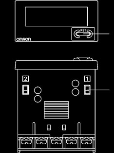
■ Operating Modes
H7EC Total Counter
Incrementing Operation (Up)
Counting display values
Reset Key
Reset the count value. Not operable under key-protect.
Counting speed switch
For all models except for H7EC-NFV-@.
The Reset Key is not operable while the
If the counting speed setting is changed,
key-protect switch is set to ON.
the present value will not be held and so press the Reset Key on the front panel.
(see note)
(see note)
(default setting)
(default setting)
Note: Perform switch setting before mounting to a control panel.
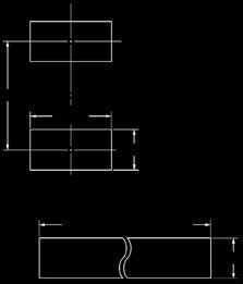
Note: All units are in millimeters unless otherwise indicated.
M3.5 terminal screw
Panel Cutout
Separate mounting
Dimensions with Y92F-34 Flush Mounting Bracket
(48 Units − 2.5) 0
Waterproofing is not possible for dense mounting
• When mounting, insert the Counter into
the cutout, insert the adapter from the back and push in the Counter while making the gap between the front panel and the cutout panel as small as possible. Use screws to secure the Counter. If waterproofing is desired, insert the waterproof packing.
• When several Counters are installed,
ensure that the ambient temperature will not exceed specifications.
• The appropriate thickness of the panel
is 1 to 5 mm.
Note: A Compact Flush Mounting Bracket (Y92F-35) can also be used. Refer to Accessories for details.
Self-powered Time Counter
New H7ET
• Seven digits, time range 0 to 3999d23.9h.
• Dual time range: 999999.9 ←→ 3999d23.9h or
999h59m59s ←→ 9999h59.9m
Model Number Structure
■ Model Number Legend
Note: Some configurations are not available.
1. Count Input
3. Case Color
None: No-voltage input
V: PNP/NPN universal DC voltage input
multi-voltage input
4. Display
2. Time Range
without backlight
1: 999h59m59s/9999h59.9m
Note: Estimates can be provided for coatings and other specifications that are not given in the datasheet. Ask your OMRON representative for details.
■ Time Counters
Timer input
Time range
999999.9h ←→ 3999d23.9h
999h59min59s ←→ 9999h59.9min
Black body
Black body
PNP/NPN universal DC volt- 7-segment LCD with back-
AC/DC multi-voltage input
(24 to 240 VAC/VDC)
■ Accessories (Order Separately)
Compact Flush Mounting Bracket
Flush Mounting Bracket (See note 1)
Wire-wrap Terminal (set of two terminals)
Lithium Battery (See note 2)
Waterproof Packing (See note 1)
Note: 1. Provided with H7ET. (Order additional Brackets separately as required.)
2. Built into H7ET. Order replacements using the above model number before the service life expires.
■ General
External/Manual reset
7-segment LCD with or without backlight, zero suppression (character height: 8.6 mm) (see note 1)
Number of digits
Time range
0.0h to 999999.9h ←→ 0.0h to 3999d23.9h
0s to 999h59min59s ←→ 0.0min to 9999h59.9min
(switchable with switch)
(switchable with switch)
Timer input
PNP/NPN univer- AC/DC multi-volt-
PNP/NPN univer- AC/DC multi-volt-
sal DC voltage in- age input
sal DC voltage in- age input
Case color
Light gray or black (-B models)
Waterproof packing, Y92F-34 Flush Mounting Bracket, time unit labels (see note 2)
UL863, CSA C22.2 No.14, LloydsConforms to EN61010-1/IEC61010-1 (pollution degree2/overvoltage category III)Conforms to VDE0106/P100
Note: 1. Only PNP/NPN universal DC voltage input models (-H models) have a backlight.
2. "-hours", "-d-h", "-h-m", and "-h-m-s" labels are included.
3. Zero suppression: Zeros are not displayed to increase readability. For example, "000008.2" is displayed as "8.2" if zero suppression is
set. If the range is set to 3999d23.9h, the value is "008.2".
■ Ratings
Backlight model: 24 VDC (0.3 W max.) Not required (powered by built-in battery)(for backlight)No-backlight model: Not required (pow-ered by built-in battery)
Timer input
High (logic) level: 4.5 to 30 VDC
High (logic) level: 24 to 240 VAC/VDC,
Low (logic) level: 0 to 2 VDC
Maximum short-circuit impedance:
(Input impedance: Approx. 4.7 kΩ)
Low (logic) level: 0 to 2.4 VAC/VDC, 50/ 10 kΩ max.
60 Hz
Short-circuit residual voltage: 0.5 V max.
Minimum open impedance: 750 kΩ min.
Reset input
No voltage inputMaximum short-circuit impedance: 10 kΩ max.
Short-circuit residual voltage: 0.5 V max.
Minimum open impedance: 750 kΩ min.
Minimum pulse
Reset system
External reset and manual reset: Minimum signal width of 20 ms
Terminal screw
0.98 N·m max.
Operating: –10°C to 55°C (with no condensation or icing)
–25°C to 65°C (with no condensation or icing)
Operating: 25% to 85%
±100 ppm (25°C)
100 MΩ min. (at 500 VDC) between
100 MΩ min. (at 500 VDC) between
100 MΩ min. (at 500 VDC) between
current-carrying metal parts and ex-
current-carrying metal parts and ex-
current-carrying metal parts and ex-
posed non-current-carrying metal
posed non-current-carrying metal
posed non-current-carrying metal
parts, and between the backlight pow- parts and between timer input termi-
er supply and timer input terminals/re- nals and reset terminalsset terminals for backlight models
1,000 VAC, 50/60 Hz for 1 min between 3,700 VAC, 50/60 Hz for 1 min between 1,000 VAC, 50/60 Hz for 1 min between current-carrying metal parts and ex-
timer input terminals and exposed non- current-carrying metal parts and ex-
posed non-current-carrying metal
current-carrying metal parts
posed non-current-carrying metal
parts and between the backlight power 2,200 VAC, 50/60 Hz for 1 min between partssupply and timer input terminals/reset reset terminals and exposed non-cur-terminals for backlight models
rent-carrying metal parts and between timer input terminals and reset termi-nals
Impulse withstand
4.5 kV between current-carrying termi- 4.5 kV between current-carrying termi- 4.5 kV between current-carrying termi-
nal and exposed non-current-carrying nal and exposed non-current-carrying nal and exposed non-current-carrying metal parts
3 kV between timer input terminals and reset terminals
Square-wave noise generated by noise simulator (pulse width: 100 ns/1 µs, 1-ns rise)±600 V (Between timer input terminals/ ±1.5 kV (Between timer input termi-
±500 V (Between timer input terminals/
Between reset terminals)
Between reset terminals)
±480 V (Between the backlight power ±500 V (Between reset terminals)supply terminals for backlight models)
±8 kV (malfunction)
Malfunction: 0.15-mm single amplitude at 10 to 55 Hz for 10 min each in 3 directionsDestruction: 0.375-mm single amplitude at 10 to 55 Hz for 2 hrs each in 3 directions
Malfunction: 200 m/s2 3 times each in 6 directionsDestruction: 300 m/s2 3 times each in 6 directions
Emission Enclosure:
EN55011 Group 1 class B
EN61000-4-2: 4 kV contact discharge (level 2)
8 kV air discharge (level 3)
Immunity RF-interference from AM Radio Waves:
EN61000-4-3: 10 V/m (80 MHz to 1 GHz) (level 3)
Immunity RF-interference from Pulse-modulated Radio Waves:
EN61000-4-3: 10 V/m (900 MHz ± 5 MHz) (level 3)
Immunity Conducted Disturbance: EN61000-4-6: 10 V (0.15 to 80 MHz) (level 3)Immunity Burst:
EN61000-4-4: 2 kV power line (level 3)
2 kV I/O signal line (level 4)
Degree of protection
IP66, NEMA4 with waterproof packing
Terminal block: IP20
Weight (see note)
No-backlight model: Approx. 60 g
Backlight model: Approx. 65 g
Note: Weight includes waterproof packing and flush mounting bracket.
■ Reference Value
10 years min. with continuous input at
The battery life is calculated according to the conditions in the left column and
25°C (lithium battery)
therefore is not a guaranteed value. Use these value as reference for mainte-nance or replacement.
■ Terminal Arrangement
Bottom view: View of the Time Counter rotated horizontally 180°
H7ET Time Counter
PNP/NPN Universal DC Voltage Input Model With Backlight
1. Contact Input (Input by a Relay or Switch Contact)
2. Solid-state Input
Open collector of a
Open collector of a
or Open collector of an
or Open collector of an
Note: 1. Terminals 2 and 4 (input circuit and reset circuit) are func-
tionally isolated.
2. Select input transistors according to the following:
Dielectric strength of the collector ≥ 50 VLeakage current < 1 µA
PNP/NPN Universal DC Voltage Input Model Without Backlight No-voltage Input Model
1. Contact Input (Input by a Relay or Switch Contact)
1. Contact Input (Input by a Relay or Switch Contact)
Terminals 2 and 4 are internally connected.
Note: Use Relays and Switches that have high contact
2. Solid-state Input
reliability because the current flowing from terminals 1
Open collector of a
Open collector of a
or 3 is as small as approx. 10 µA. It is recommended
that OMRON's G3TA-IA/ID be used as the SSR.
2. Solid-state Input (Open Collector Input of an NPN Transistor)
Open collector of an
Open collector of an
Terminals 2 and 4 are
or Open collector of an
or Open collector of an
Note: 1. Residual voltage in the output section of Proximity
Sensors or Photoelectric Sensors becomes less than 0.5 V because the current flowing from terminals 1 or 3 is as small as approx. 10 µA, thus allowing easy connection.
Note: 1. Terminals 2 and 4 (input circuit and reset circuit) are
2. Select input transistors according to the following:
Dielectric strength of the collector ≥ 50 V
2. Select input transistors according to the following:
Leakage current < 1 µA
Dielectric strength of the collector ≥ 50 V
Leakage current < 1 µA
AC/DC Multi-voltage Input Model
or Open collector of an NPN transistor


■ Operating Modes
H7ET Time Counter
Incrementing Operation (Up)
Internal clock timer value
Timer display values
Location to Attach
Unit Label
Attach the correct unit
label for the time range
Reset Key
that is set.
Reset the count value. Not operable under key-protect.
Time-range switch
Key-protect Switch
If the time-range setting is
The Reset Key is not operable while the
changed, the present
key-protect switch is set to ON.
value will not be held and so press the Reset Key on
(see note)
Key-protect
the front panel.
Time range
(see note)
(default setting)
0.0h to 3999d23.9h
0s to 999h59min59s
(default setting)
0.0h to 999999.9h 0.0min to 9999h59.9min
(default setting)
Display Values for a Time Range of "0.0h to 3999d23.9h"
If the time-range switch is set to "0.0h to 3999d23.9h," the four leftmost digits are the number of days and the three rightmost
digits are the number of hours.
The initial value after resetting is 000.00 (0 days, 00.0 hours).
After "023.9" (0 days, 23.9 hours), the display will change to "100.0" (1 days, 00.0 hours).
LCD Examples for "0.0h to 3999d23.9h" Range
Note: Perform switch setting before mounting to a control panel.
Note: All units are in millimeters unless otherwise indicated.
Panel Cutout
Separate mounting
Dimensions with Y92F-34 Flush Mounting Bracket
(48 Units − 2.5) 0
Waterproofing is not possible for dense mounting
• When mounting, insert the Counter into
the cutout, insert the adapter from the back and push in the Counter while making the gap between the front panel and the cutout panel as small as possible. Use screws to secure the Counter. If waterproofing is desired, insert the waterproof packing.
• When several Counters are installed,
ensure that the ambient temperature will not exceed specifications.
• The appropriate thickness of the panel
is 1 to 5 mm.
Note: A Compact Flush Mounting Bracket (Y92F-35) can also be used. Refer to Accessories for details.
Self-powered Tachometer
New H7ER
• Revolutions displayed up to five digits.
• Dual revolution display according to encoder resolution used;
1000 s–1/1000 min–1 or 1000.0 s–1 /1000.0 min–1
• Switchable dual revolution display type available (-NV1 models);
extended up to 10000 min–1
Model Number Structure
■ Model Number Legend
Note: Some configurations are not available.
1. Count Input
3. Case Color
None: No-voltage input
V: PNP/NPN universal DC voltage input
2. Number of Digits
4. Display
without backlight
Note: Estimates can be provided for coatings and other specifications that are not given in the datasheet. Ask your OMRON representative for details.
Count input
Max. revolutions displayed (applicable encoder resolution)
1000 s–1 (1 pulse/rev.),
1000.0 s–1 (10 pulse/rev.),
1000 min–1 (60 pulse/rev.)
1000.0 min–1 (600 pulse/rev.) ←→
10000 min–1 (60 pulse/rev.) (switchable)
Black body
Black body
PNP/NPN universal 7-segment LCD
■ Accessories (Order Separately)
Compact Flush Mounting Bracket
Flush Mounting Bracket (See note 1)
Wire-wrap Terminal (set of two terminals)
Lithium Battery (See note 2)
Waterproof Packing (See note 1)
Note: 1. Provided with H7ER. (Order additional Brackets separately as required.)
2. Built into H7ER. Order replacements using the above model number before the service life expires.
■ General
Screw terminals, Wire-wrap Terminals (see note 3)
7-segment LCD with or without backlight, zero suppression (character height: 8.6 mm) (see note 4)
Number of digits
Count input
PNP/NPN universal DC
PNP/NPN universal DC voltage input
Max. counting speed
Max. revolutions displayed
1,000 s–1 (When encoder resolution of 1 pulse/rev is 1,000.0 s–1 (When encoder resolution of 10 pulse/rev
(see note 5)
1,000 min–1 (When encoder resolution of 60 pulse/
1,000.0 min–1 (When encoder resolution of
600 pulse/rev is used.)←→ 10,000 min–1 (When encoder resolution of 60 pulse/rev is used.)(Switchable with switch)
Waterproof packing, Y92F-34 Flush Mounting Bracket, revolution unit labels (see note 5)
UL863, CSA C22.2 No.14, LloydsConforms to EN61010-1/IEC61010-1 (Pollution degree2/overvoltage category III)Conforms to VDE0106/P100
Note: 1. Reset is not available.
2. When there is no input, the display will be 0.0 or 0.
3. Separately ordered Wire-wrap Terminals (Y92S-37) are required.
4. Only PNP/NPN Universal DC voltage input models have a backlight.
5. "rpm", "rps", "s–1" and "min–1" labels are included.
■ Ratings
Backlight model: 24 VDC (0.3 W max.) (for backlight Not required (powered by built-in battery)lit)No-backlight model: Not required (powered by built-in battery)
Count input
High (logic) level: 4.5 to 30 VDC
Low (logic) level: 0 to 2 VDC
Maximum short-circuit impedance: 10 kΩ max.
(Input impedance: Approx. 4.7 kΩ)
Short-circuit residual voltage: 0.5 V max.
Minimum open impedance: 750 kΩ min.
Max. counting speed
4-digit models:1 kHz
5-digit models:10 kHz
Minimum signal width
10 kHz: 0.05 ms1 kHz: 0.5 ms (See note.)
Terminal screw tightening torque 0.98 N·m max.
Operating: –10°C to 55°C (with no condensation or icing)Storage:
–25°C to 65°C (with no condensation or icing)
Operating: 25% to 85%
Note: 5-digit models :1 kHz/10 kHz switchable.
100 MΩ min. (at 500 VDC) between current-carrying 100 MΩ min. (at 500 VDC) between current-carrying metal parts and exposed non-current-carrying metal metal parts and exposed non-current-carrying metal parts, and between the backlight power supply and partscount input terminals/reset terminals for backlight models
1,000 VAC, 50/60 Hz for 1 min between current-car- 1,000 VAC, 50/60 Hz for 1 min between current-car-rying metal parts and exposed non-current-carrying rying metal parts and exposed non-current-carrying metal parts and between the backlight power supply metal partsand count input terminals/reset terminals for back-light models
Impulse withstand voltage
4.5 kV between current-carrying terminal and exposed non-current-carrying metal parts
Square-wave noise generated by noise simulator (pulse width: 100 ns/1 µs, 1-ns rise)±600 V (Between count input terminals)
±500 V (Between count input terminals)
±480 V (Between the backlight power supply termi-nals for backlight models)
±8 kV (malfunction)
Malfunction: 0.15-mm single amplitude at 10 to 55 Hz for 10 min each in 3 directionsDestruction: 0.375-mm single amplitude at 10 to 55 Hz for 2 hrs each in 3 directions
Malfunction: 200 m/s2 3 times each in 6 directionsDestruction: 300 m/s2 3 times each in 6 directions
Emission Enclosure:
EN55011 Group 1 class B
EN61000-4-2: 4 kV contact discharge (level 2)
8 kV air discharge (level 3)
Immunity RF-interference from AM Radio Waves:
EN61000-4-3: 10 V/m (80 MHz to 1 GHz) (level 3)
Immunity RF-interference from Pulse-modulated Radio Waves:
EN61000-4-3: 10 V/m (900 MHz ± 5 MHz) (level 3)
Immunity Conducted Disturbance: EN61000-4-6: 10 V (0.15 to 80 MHz) (level 3)Immunity Burst:
EN61000-4-4: 2 kV power line (level 3)
2 kV I/O signal line (level 4)
Degree of protection
IP66, NEMA4 with waterproof packing
Terminal block: IP20
Weight (see note)
No-backlight model:Approx. 60 gBacklight model:
Note: Weight includes waterproof packing and flush mounting bracket.
■ Reference Value
7 years min. with continuous input at 25°C The battery life is calculated according to the conditions in the left column and (lithium battery)
therefore is not a guaranteed value. Use these value as reference for mainte-nance or replacement.
■ Terminal Arrangement
Bottom view: View of the Tachometer rotated horizontally 180°
Note: Select input transistors according to the following:
Dielectric strength of the collector ≥ 50 VLeakage current < 100 µA (1 µA for no-voltage input model)
PNP/NPN Universal DC Voltage Input Models With Backlight
No-voltage Input Model
Transistor Input (Open Collector of an NPN Transistor)
Open collector of
Open collector of
Open collector of
an NPN transistor
an PNP transistor
an NPN transistor
PNP/NPN Universal DC Voltage Input Models Without Backlight
Transistor Input
Open collector of
Open collector of
an NPN transistor
an PNP transistor
■ Operating Modes
Incrementing Operation Within Unit Time (Up)
Display refreshed
Internal count value
Display refreshed Display refreshed every 1.25 s
Applicable unit label
Counting speed switch
Counting Speed Switch Settings and Unit Label Application
Counting speed Max. revolutions Applicable encoder Applicable unit
switch setting
displayed
resolution
(see note)
"min-1" or "rpm"
(default setting)
"min-1" or "rpm"
"s-1" or "rps"
"min-1" or "rpm"
H7ER-N-@
"s-1" or "rps"
Note: Perform switch setting before mounting to a control panel.
Note: All units are in millimeters unless otherwise indicated.
Panel Cutout
Separate mounting
Dimensions with Y92F-34 Flush Mounting Bracket
(48 Units − 2.5) 0
Waterproofing is not possible for dense mounting
• When mounting, insert the Counter into
the cutout, insert the adapter from the back and push in the Counter while making the gap between the front panel and the cutout panel as small as possible. Use screws to secure the Counter. If waterproofing is desired, insert the waterproof packing.
• When several Counters are installed,
ensure that the ambient temperature will not exceed specifications.
• The appropriate thickness of the panel
is 1 to 5 mm.
Note: A Compact Flush Mounting Bracket (Y92F-35) can also be used. Refer to Accessories for details.
• Dedicated for use on PCB.
• Total Counters and Time Counter available.
Model Number Structure
■ Model Number Legend
1. Function
2. Max. Counting Speed for H7EC Models
■ PC Board-use Counters
Count input
Time counter
Max. counting speed
■ Accessory (Order Separately)
Connecting Socket (28-pin)
■ General
Time Counter
Direct mounting on PC Board or mounting on 28-pin socket
External reset, Power-OFF reset
Number of digits
Time range
0.0h to 999999.9h
Max. counting speed
7-segment LCD (character height: 8.6 mm)
Case color
UL863, CSA C22.2 No.14
■ Ratings
3 VDC (2.7 to 3.3 VDC)
No voltage inputMaximum short-circuit impedance: 10 kΩ max.
Reset input
Short-circuit residual voltage: 0.5 V max.
Minimum open impedance: 750 kΩ min.
Max. counting speed (see note)
1 kHz: Minimum signal width of 0.5 ms
30 Hz: Minimum signal width of 16.7 ms
Minimum signal input width
Reset system
External reset: Minimum signal width of 20 msPower-OFF reset: Minimum power OFF time of 500 ms
Operating: –10°C to 55°C (with no condensation or icing)Storage:
–25°C to 65°C (with no condensation or icing)
Operating: 25% to 85%
Note: ON/OFF ratio 1:1
±100 ppm (25°C)
Square-wave noise generated by noise simulator (pulse width: 100 ns/1 µs, 1-ns rise)±500 V (Between count or timer input terminals/Between reset terminals)
±8 kV (malfunction)
Malfunction:0.15-mm single amplitude at 10 to 55 Hz for 10 min each in 3 directionsDestruction:0.375-mm single amplitude at 10 to 55 Hz for 2 hrs each in 3 directions
Malfunction:200 m/s2 3 times each in 6 directionsDestruction:300 m/s2 3 times each in 6 directions
Emission Enclosure:
EN55011 Group 1 class B
EN61000-4-2: 4-kV contact discharge (level 2)
8-kV air discharge (level 3)
Immunity RF-interference from AM Radio Waves:
EN61000-4-3: 10 V/m (80 MHz to 1 GHz) (level 3)
Immunity RF-interference from Pulse-modulated Radio Waves:
EN61000-4-3: 10 V/m (900 MHz ± 5 MHz) (level 3)
Immunity Conducted Disturbance (see note):EN61000-4-6: 10 V (0.15 to 80 MHz) (level 3)Immunity Burst (see note):
EN61000-4-4: 2-kV I/O signal line (level 4)
Note: The power supply terminals of the H7E@-N@P are considered as 3-VDC control terminals.
■ Terminal Arrangement
Power Supply and Battery Connections
Backup Circuit for Protection Against Power Failure
When designing a circuit, keep the power wiring connections shorter than 50mm. Refer to the connection diagram above for the proper wiring polarity.
Use a diode (D) having a forward voltage as small as possible (0.1 V
The life expectancy of a battery power supply can be calculated by
max. at IF of 20 μA).
the following formula:
Determine the ratio of R1 to R2 in accordance with the forward volt-
age of the diode to be used. Be aware that when the power supplied
to the H7E@-N@P has dropped to less than the voltage of the
Life expectancy of battery (h)
backup circuit, the battery will discharge.
A: Battery capacity (mAh)
To protect the circuit against a momentary power failure, an aluminum
lc: H7E@-N@P current consumption (mA)
electrolyte capacitor can be used in place of a battery, as shown below:
Example:Battery life when using a 3-V lithium battery with a capacity of1,200 mAh for the H7E@-N@P.
t = 1,200 [mAh]/20 × 10–3 [mA] = 60,000 hours (approx. 6.8 years)The battery capacity varies depending on the type of battery used;oxidized silver, mercury, or lithium battery.
Voltage Division of Power Supply Circuit
When necessary, the voltage from the battery may be divided by resistances:
When a capacitor is used, its backup time can be calculated by thefollowing formula:
C: Capacitance (μF)V1: Supply voltage before power failure (V)V2: Minimum operating voltage of H7E@-N@P (V)Ic: H7E@-N@P current consumption (μA)
When doing so, however, ensure that the following equation balances:
Backup time by an aluminum electrolytic capacitor of 100 μF. (Mini-
mum operating voltage of H7E@-N@P is 2.6 V.)
t = 100 μF × (3–2.6 V)/20 μA = 100 × 0.40/20 = 2.0 seconds
Note that the above calculation provides an approximate value,
which varies depending on the environment under which the Counter
is used and also on the type of capacitors used. Provide some allow-ance in selecting capacitors.
Allow a current high enough to flow through R1 so that the H7E@-
Keep the wiring between the H7E@-N@P and R
N@P receives sufficient current.
2 or C as short as
possible (within 50 mm).
C is a film capacitor, of about 0.1 μF, and is intended to absorb noise
induced by the power lines.
Keep the wiring between the H7E@-N@P and R2 or C as short aspossible (within 50 mm).
Solid State Input
Open-collector Transistor Input
Input Connection Contact Input
Count/Timer input
Count/Timer input
TTL or C-MOS IC Input
When the H7EC-NP is used, relay chattering may be counted. Usethe H7EC-NLP, one of the low-speed input models.
Count/Timer input
Use a transistor for input that satisfies the following conditions:
Collector breakdown voltage ≥ 50 VLeakage current < 1 µA
Use a diode (D) having a forward voltage as small as possible (0.1 Vmax. at IF of 20 µA).
■ Operating Modes
H7EC Total Counter
H7ET Time Counter
Incrementing Operation
Incrementing Operation
Counting display values
Timer display values
Note: All units are in millimeters unless otherwise indicated.
DIP Terminal
PCB Processing Dimensions
Section occupied
Eight, 0.8 dia.
Note: Processing dimensions are
for 28-pin IC socket.
Accessories (Order Separately) (Common)
■ New H7E (Except for PCB-mounting Counter)
The New H7E models are supplied with a mounting bracket (Y92F-34) and nut. Additionally, the Y92F-75/-76/-77B Flush Mounting Adapters shown
here allow the New H7E models to be fitted to existing panel cutouts.
Y92F-35 Compact Flush Mounting Bracket
Panel Cutout
(48 × No. of units
Degree of protection (front): IP40 (not waterproof)
• The minimum mounting interval is 30 mm.
The DIP switch of the H7E@-N can be operated in mounted condi-
Note: An interval of 40 mm is recommended for easier wiring.
tion. Vibration resistance and shock resistant are the same level as
• Do not allow the ambient temperature of the H7E@-N to exceed the
the H7E@-N series.
• Mounting is possible onto panels with a thickness of 1 to 5 mm.
Y92F-75 Flush Mounting Adapter
for 26 × 45.3 Rectangular Cutout
Use mounting bracket supplied with the Counter
Two 3.5 dia. mounting holes
Panel Cutout
(Color: light gray)
Y92F-76 Flush Mounting Adapter
for 27.5 × 52.5 Rectangular Cutout
Panel Cutout
Two 4.5 dia. countersunk holes
(Color: light gray)
Use the Y92F-76 together with the Y92F-35 Compact
Flush Mounting Bracket.
Do not use the Flush Mounting Adapter supplied with the Counter.
Y92F-77B Flush Mounting Adapter
for 24.8 × 48.8 Rectangular Cutout
Use mounting bracket supplied with the Counter
Panel cutout
(Color: light gray)
Note: The mounting panel
thickness should be between 1 and 5 mm.
Y92S-37 Wire-wrap Terminal (Set of Two Terminals)
Wire-wrap terminal (1 × 1 mm)
When using the Wire-wrap Terminal, be sure to use the correct wires
and peripheral devices. (The correct wires, bits and sleeves areshown in the table on the right.)
Y92S-36 Lithium Battery (3 V)
Refer to Safety Precautions for All Counters.
■ New H7E (Except for PCB-mounting Counter)
!WARNING
!CAUTION
This product has a built-in lithium battery. Do not short-circuit the +
If a voltage other than the rated one is applied, internal elements may
and − terminals, charge, disassemble, deform, or expose the battery
to fire. The battery may explode (break), catch fire, or cause liquid
Do not use the Counter in the following places:
• Locations subject to direct sunlight.
• Locations subject to corrosive gases.
Do not use any battery other than the specified one (Y92S-36). Using
• Locations subject to dust.
another battery may cause liquid leakage or breakage, resulting in malfunction or injury.
Before Use
Reset Input and Count/Timer Input
• An insulation sheet has been inserted to maintain the quality of the
• The H7E operates using its built-in Battery. If the H7E is connected
Totalizer in the event of a long period without use. Be sure to
to a device that has +V and OUT terminals that are connected with
remove this sheet before attempting to use the product.
a diode as shown in the circuit diagram, the circuit indicated by the
Remove the insulation sheet and press the Reset Key on the front
arrow 1 or 2 will be formed when the device is turned OFF. As a
panel of the Counter. (With the H7ER-N,-NV(-H),-NV1(-H), models,
result, the H7E may be reset or count by one. It is recommended
"0" or "0.0" will be displayed after 1 s.)
that such devices not be connected to the H7E.
input or reset input
• Switch settings on the Counter must be performed before mounting
• If an excessive voltage is applied to the count/timer input or reset
it to a control panel.
input terminals, the internal elements may be damaged.
• Do not use the Counter in the following locations:
Ensure that the following voltages are not exceeded:
• Locations subject to severe changes in temperature.
• PNP/NPN universal voltage input model: 30 VDC
• Locations subject to condensation as the result of high humidity.
• AC/DC voltage input model:
At count/timer input: 240 VAC (peak voltage: 338V)
Mounting Precautions for Flush
No voltage can be applied. (No-voltage
• No-voltage input model: No voltage can be applied.
Although the operating section is watertight (conforming to NEMA4,
• Avoid wiring close to high-tension or large-current lines.
IP66), rubber packing is provided to avoid water leakage through thegap between the Counter and panel cutout. Unless this rubber pack-
• Do not remove the outer case when voltage is being applied to the
ing is tightly squeezed on, water may permeate inside the panel.
power supply terminals or the input terminals.
Therefore, be sure to tighten the screws for fixing the Y92F-34 Flush
• The input for the H7E@-NFV-@ is a high-impedance circuit and so
Mounting Bracket. (Excessive tightening may also deform the rubber
influence from an induced voltage may result in malfunction. There-
fore, when the input signal wiring is longer than 10 m (line capaci-tance of 120 pF/m, at room temperature), it is recommended that a
Screw for the Flush Mounting Bracket
CR filter or a bleeder resistor is connected.
The wider side must
face the panel.
Count Input, Timer Input or Reset Input
AC/DC Multi-voltage Input Models
to More than One H7E Counter at a
• When connecting count/timer input from an SSR to the Counter
that operates with AC/DC voltage input, use OMRON's G3TA-IA/ID
SSR (for DC) whose leakage current is 0.1 mA max. or connect ableeder resistor in parallel to the input circuit of the Counter.
• PNP/NPN Universal DC Voltage Input
Leakage current: 0.1 mA max.
*Bleeder resistor The voltage between terminals 1 and 2 must be
1.5 V maximum when the SSR is OFF.
Backlight Power Supply
• To reduce variation in the brightness of the backlight when using
more than one H7E with a backlight, use the same power supply forall the backlights.
Note: H (Reset ON) level must be 4.5 V minimum.
H = 4.7 (kΩ)/N + R
• No-voltage Input
• When connecting the DC power supply for the backlights, be sure
to connect the polarities correctly.
Input Verification with the H7ET Time
Counter
Note: 1. The leakage current of the transistor used for input must be
less than 1 µA.
(When the time range is not set to 0s to
2. The forward voltage of the diode must be as low as possible
(i.e., 0.1 V maximum with an IF of 20 µA) so that the voltagebetween terminals 3 and 4 will be 0.5 V when the reset input
The decimal point of the LCD blinks every other second while an
input signal is being applied. If the decimal point is not blinking, theinput signal is not being received correctly. Check the input signal
Input and Power Supply
Unit Label for Time Counter and
No-voltage Input Models
• Do not impose voltage on the Counter if the Counter is a model that
operates with no-voltage input, otherwise the internal circuit of the
A unit label has been packed with the Counter. Use in accordance
Counter may be damaged.
with the application.
Do not connect any single input signal in parallel to Counter modelsoperating with no-voltage input and those operating with voltage
input, otherwise the Counters may malfunction.
• When connecting a sensor to the Counter that operates with no-
voltage input, make sure that the sensor has open collector output.
Remove the wiring when replacing the Battery. Do not come in con-
tact with any item to which high voltage is being applied. Doing somay result in electric shock.
• When connecting an open collector input from a transistor to the
Before changing the Battery, the person should ensure that they are
Counter that operates with no-voltage input, make sure that the
not carrying any static electric charge.
leakage current of the transistor is 1 µA maximum.
Procedure for replacing the Battery (refer to the diagrams below):
No-voltage Input and PNP/NPN Universal DC
1. Using the tool, pry open the lift-tab on the case. (1)
Voltage Input Models
2. Pull the body out of its outer case. (2)
3. Lift the Battery up by the edge and remove it. (3)
• The operation of the Counter may be affected if the capacitance of
When removing the Battery, do not come in contact with the dis-
input lines exceeds 500 pF (about 10 m, with parallel wires of 2 x
play area or any internal parts.
4. Wipe the back of the new Battery before inserting it.
Keep all wires as short as possible. When using shielded wire, linecapacitance may occur.
5. Ensure that the + and – terminals are correctly oriented.
6. After replacing the Battery, re-insert the body into its case. (4)
Check that the case is securely held in by the lift-tab.
7. Press the Reset Key before use (not necessary for H7ER-N,-NV,-
The count or timer input, reset input, and backlight power supply ter-
minals of the no-voltage input or PNP/NPN universal DC voltage
input models (H7E@-N,-N1, H7E@-NV(-H),-NV1(-H)) are not iso-lated.
A SELV power supply conforming to Appendix H of IEC61010-1should be used for the count or timer input, reset input and backlightpower supply terminals. A SELV power supply is a power supply forwhich the input and output have double or reinforced insulation, and
for which the output voltage is 30 Vrms with 42.4 V peak or 60 VDCmax. (Only the H7E@-NV@-H has a backlight.)
The terminals for count or timer input and reset input for AC/DCmulti-voltage input models have basic insulation.
Connect the reset input terminals to a device that does not haveexposed current-carrying parts and has basic insulation for 240 VAC.
If the indicator keeps flickering or is OFF, the internal battery may beclose to the end of its service life. In such a case, it is suggested thatthe battery be replaced.
■ PCB-mounting Counter
Power Supply
• Use the power supply within the applicable range indicated by the
To prevent unwanted reset when replacing the battery, connect the
following waveform, while considering the ripple and voltage fluctu-
new battery before disconnecting the old one. Otherwise, the voltage
ations of the circuit power source.
supplied to the counter circuit drops, causing the present count valueto reset.
When designing the circuit board, providing two extra terminals forbattery connection will make the switch must simpler. See the sche-
matic diagram below:
• The H7E@-N@P changes its mode as shown below depending on
the applied supply voltage.
Internal circuit
Wiring polarity must be carefully observed, in order to prevent per-
Beyond supply voltage
manent damage to the Counters. Exercise caution when inserting
the Counter in the socket, to prevent reversed polarity.
PC Board (Bad Example)
PC Board (Good Example)
Do not route the wiring of the count, timer, or reset inputs in the vicin-ity of, or in parallel to the wiring of high-voltage or inductive load cir-
cuits (such as motors and relays). Also, keep the wiring as short as
Placed far away from
the power supply.
consuming components
Wired in parallel with large-current-carrying
When using the Counter in an environment where the Counter issubject to frequent occurrences of vibration or shock, or whenmounting the Counter facing downwards or sideways, it is suggested
Be careful not to apply voltages exceeding the following values to the
that the Counter be directly soldered to a PCB instead of using sock-
count, timer, or reset terminals, otherwise the internal circuit may be
No-voltage input: 3 VDC
To Conform to EN/IEC Standards
Input terminals have no insulation from power supply terminals. The
power supply terminals must be supplied from a SELV source inaccordance with IEC61010-1 Annex H. SELV (separated extra-low
Finish soldering under the conditions below.
voltage) source is a power supply having double or reinforced insula-
Solder the terminals within 5 seconds, at a solder iron tip tempera-
tion between the primary and the secondary circuit and having out-
ture of 250°C ± 10°C when using lead solder, and within 3 seconds,
put voltage of 30 V rms max. and 42.4 V peak max. or 60 VDC max.
at a solder iron tip temperature of 350°C ± 10°C when using lead-free solder.
Since the Counter is not flux-tight, do not use flux when soldering.
To prevent damage, the exterior of the Counter must not be exposed
Avoid automatic and dip soldering. Manually solder the Counter onto
to organic solvents (3.g. paint thinner or benzine), strong alkalis, or
a PC board, and avoid cleaning as much as possible.
strong acids.
When mounting the Counter on a PC board with components whichconsume higher current than the H7E@-N@P, observe the following
• No user-serviceable parts.
1. Minimize the wiring (less than 50 mm) from the H7E@-N@P to the
• Return to OMRON for all repairs.
power supply section.
2. Avoid placing the H7E@-N@P power, timer, counter, or reset input
circuit in parallel with circuits that consume large currents, partic-ularly on the positive side.
ALL DIMENSIONS SHOWN ARE IN MILLIMETERS.
To convert millimeters into inches, multiply by 0.03937. To convert grams into ounces, multiply by 0.03527.
In the interest of product improvement, specifications are subject to change without notice.
Terms and Conditions of Sale
Offer; Acceptance. These terms and conditions (these "Terms") are deemed
ITY OR FITNESS FOR A PARTICULAR PURPOSE OF THE PRODUCTS.
part of all quotes, agreements, purchase orders, acknowledgments, price lists,
BUYER ACKNOWLEDGES THAT IT ALONE HAS DETERMINED THAT THE
catalogs, manuals, brochures and other documents, whether electronic or in
PRODUCTS WILL SUITABLY MEET THE REQUIREMENTS OF THEIR
writing, relating to the sale of products or services (collectively, the "Products")
INTENDED USE. Omron further disclaims all warranties and responsibility of
by Omron Electronics LLC and its subsidiary companies ("Omron"). Omron
any type for claims or expenses based on infringement by the Products or oth-
objects to any terms or conditions proposed in Buyer's purchase order or other
erwise of any intellectual property right. (c) Buyer Remedy. Omron's sole obli-
documents which are inconsistent with, or in addition to, these Terms.
gation hereunder shall be, at Omron's election, to (i) replace (in the form
Prices; Payment Terms. All prices stated are current, subject to change with-
originally shipped with Buyer responsible for labor charges for removal or
out notice by Omron. Omron reserves the right to increase or decrease prices
replacement thereof) the non-complying Product, (ii) repair the non-complying
on any unshipped portions of outstanding orders. Payments for Products are
Product, or (iii) repay or credit Buyer an amount equal to the purchase price of
due net 30 days unless otherwise stated in the invoice.
the non-complying Product; provided that in no event shall Omron be responsi-
Discounts. Cash discounts, if any, will apply only on the net amount of invoices
ble for warranty, repair, indemnity or any other claims or expenses regarding
sent to Buyer after deducting transportation charges, taxes and duties, and will
the Products unless Omron's analysis confirms that the Products were prop-
be allowed only if (i) the invoice is paid according to Omron's payment terms
erly handled, stored, installed and maintained and not subject to contamina-
and (ii) Buyer has no past due amounts.
tion, abuse, misuse or inappropriate modification. Return of any Products by
Interest. Omron, at its option, may charge Buyer 1-1/2% interest per month or
Buyer must be approved in writing by Omron before shipment. Omron Compa-
the maximum legal rate, whichever is less, on any balance not paid within the
nies shall not be liable for the suitability or unsuitability or the results from the
stated terms.
use of Products in combination with any electrical or electronic components,
Orders. Omron will accept no order less than $200 net billing.
circuits, system assemblies or any other materials or substances or environ-
Governmental Approvals. Buyer shall be responsible for, and shall bear all
ments. Any advice, recommendations or information given orally or in writing,
costs involved in, obtaining any government approvals required for the impor-
are not to be construed as an amendment or addition to the above warranty.
tation or sale of the Products.
See http://www.omron247.com or contact your Omron representative for pub-
Taxes. All taxes, duties and other governmental charges (other than general
lished information.
real property and income taxes), including any interest or penalties thereon,
14. Limitation on Liability; Etc. OMRON COMPANIES SHALL NOT BE LIABLE
imposed directly or indirectly on Omron or required to be collected directly or
FOR SPECIAL, INDIRECT, INCIDENTAL, OR CONSEQUENTIAL DAMAGES,
indirectly by Omron for the manufacture, production, sale, delivery, importa-
LOSS OF PROFITS OR PRODUCTION OR COMMERCIAL LOSS IN ANY
tion, consumption or use of the Products sold hereunder (including customs
WAY CONNECTED WITH THE PRODUCTS, WHETHER SUCH CLAIM IS
duties and sales, excise, use, turnover and license taxes) shall be charged to
BASED IN CONTRACT, WARRANTY, NEGLIGENCE OR STRICT LIABILITY.
and remitted by Buyer to Omron.
Further, in no event shall liability of Omron Companies exceed the individual
Financial. If the financial position of Buyer at any time becomes unsatisfactory
price of the Product on which liability is asserted.
to Omron, Omron reserves the right to stop shipments or require satisfactory
15. Indemnities. Buyer shall indemnify and hold harmless Omron Companies and
security or payment in advance. If Buyer fails to make payment or otherwise
their employees from and against all liabilities, losses, claims, costs and
comply with these Terms or any related agreement, Omron may (without liabil-
expenses (including attorney's fees and expenses) related to any claim, inves-
ity and in addition to other remedies) cancel any unshipped portion of Prod-
tigation, litigation or proceeding (whether or not Omron is a party) which arises
ucts sold hereunder and stop any Products in transit until Buyer pays all
or is alleged to arise from Buyer's acts or omissions under these Terms or in
amounts, including amounts payable hereunder, whether or not then due,
any way with respect to the Products. Without limiting the foregoing, Buyer (at
which are owing to it by Buyer. Buyer shall in any event remain liable for all
its own expense) shall indemnify and hold harmless Omron and defend or set-
unpaid accounts.
tle any action brought against such Companies to the extent based on a claim
Cancellation; Etc. Orders are not subject to rescheduling or cancellation
that any Product made to Buyer specifications infringed intellectual property
unless Buyer indemnifies Omron against all related costs or expenses.
rights of another party.
10. Force Majeure. Omron shall not be liable for any delay or failure in delivery
16. Property; Confidentiality. Any intellectual property in the Products is the exclu-
resulting from causes beyond its control, including earthquakes, fires, floods,
sive property of Omron Companies and Buyer shall not attempt to duplicate it
strikes or other labor disputes, shortage of labor or materials, accidents to
in any way without the written permission of Omron. Notwithstanding any
machinery, acts of sabotage, riots, delay in or lack of transportation or the
charges to Buyer for engineering or tooling, all engineering and tooling shall
requirements of any government authority.
remain the exclusive property of Omron. All information and materials supplied
11. Shipping; Delivery. Unless otherwise expressly agreed in writing by Omron:
by Omron to Buyer relating to the Products are confidential and proprietary,
a. Shipments shall be by a carrier selected by Omron; Omron will not drop ship
and Buyer shall limit distribution thereof to its trusted employees and strictly
except in "break down" situations.
prevent disclosure to any third party.
b. Such carrier shall act as the agent of Buyer and delivery to such carrier shall
17. Export Controls. Buyer shall comply with all applicable laws, regulations and
constitute delivery to Buyer;
licenses regarding (i) export of products or information; (iii) sale of products to
c. All sales and shipments of Products shall be FOB shipping point (unless oth-
"forbidden" or other proscribed persons; and (ii) disclosure to non-citizens of
erwise stated in writing by Omron), at which point title and risk of loss shall
regulated technology or information.
pass from Omron to Buyer; provided that Omron shall retain a security inter-
18. Miscellaneous. (a) Waiver. No failure or delay by Omron in exercising any right
est in the Products until the full purchase price is paid;
and no course of dealing between Buyer and Omron shall operate as a waiver
d. Delivery and shipping dates are estimates only; and
of rights by Omron. (b) Assignment. Buyer may not assign its rights hereunder
e. Omron will package Products as it deems proper for protection against nor-
without Omron's written consent. (c) Law. These Terms are governed by the
mal handling and extra charges apply to special conditions.
law of the jurisdiction of the home office of the Omron company from which
12. Claims. Any claim by Buyer against Omron for shortage or damage to the
Buyer is purchasing the Products (without regard to conflict of law princi-
Products occurring before delivery to the carrier must be presented in writing
ples). (d) Amendment. These Terms constitute the entire agreement between
to Omron within 30 days of receipt of shipment and include the original trans-
Buyer and Omron relating to the Products, and no provision may be changed
portation bill signed by the carrier noting that the carrier received the Products
or waived unless in writing signed by the parties. (e) Severability. If any provi-
from Omron in the condition claimed.
sion hereof is rendered ineffective or invalid, such provision shall not invalidate
13. Warranties. (a) Exclusive Warranty. Omron's exclusive warranty is that the
any other provision. (f) Setoff. Buyer shall have no right to set off any amounts
Products will be free from defects in materials and workmanship for a period of
against the amount owing in respect of this invoice. (g) Definitions. As used
twelve months from the date of sale by Omron (or such other period expressed
herein, "including" means "including without limitation"; and "Omron Compa-
in writing by Omron). Omron disclaims all other warranties, express or implied.
nies" (or similar words) mean Omron Corporation and any direct or indirect
(b) Limitations. OMRON MAKES NO WARRANTY OR REPRESENTATION,
subsidiary or affiliate thereof.
EXPRESS OR IMPLIED, ABOUT NON-INFRINGEMENT, MERCHANTABIL-
Certain Precautions on Specifications and Use
Suitability of Use. Omron Companies shall not be responsible for conformity
ADDRESS THE RISKS, AND THAT THE OMRON'S PRODUCT IS PROP-
with any standards, codes or regulations which apply to the combination of the
ERLY RATED AND INSTALLED FOR THE INTENDED USE WITHIN THE
Product in the Buyer's application or use of the Product. At Buyer's request,
OVERALL EQUIPMENT OR SYSTEM.
Omron will provide applicable third party certification documents identifying
Programmable Products. Omron Companies shall not be responsible for the
ratings and limitations of use which apply to the Product. This information by
user's programming of a programmable Product, or any consequence thereof.
itself is not sufficient for a complete determination of the suitability of the Prod-
Performance Data. Data presented in Omron Company websites, catalogs
uct in combination with the end product, machine, system, or other application
and other materials is provided as a guide for the user in determining suitabil-
or use. Buyer shall be solely responsible for determining appropriateness of
ity and does not constitute a warranty. It may represent the result of Omron's
the particular Product with respect to Buyer's application, product or system.
test conditions, and the user must correlate it to actual application require-
Buyer shall take application responsibility in all cases but the following is a
ments. Actual performance is subject to the Omron's Warranty and Limitations
non-exhaustive list of applications for which particular attention must be given:
(i) Outdoor use, uses involving potential chemical contamination or electrical
Change in Specifications. Product specifications and accessories may be
interference, or conditions or uses not described in this document.
changed at any time based on improvements and other reasons. It is our prac-
(ii) Use in consumer products or any use in significant quantities.
tice to change part numbers when published ratings or features are changed,
(iii) Energy control systems, combustion systems, railroad systems, aviation
or when significant construction changes are made. However, some specifica-
systems, medical equipment, amusement machines, vehicles, safety equip-
tions of the Product may be changed without any notice. When in doubt, spe-
ment, and installations subject to separate industry or government regulations.
cial part numbers may be assigned to fix or establish key specifications for
(iv) Systems, machines and equipment that could present a risk to life or prop-
your application. Please consult with your Omron's representative at any time
erty. Please know and observe all prohibitions of use applicable to this Prod-
to confirm actual specifications of purchased Product.
Errors and Omissions. Information presented by Omron Companies has been
NEVER USE THE PRODUCT FOR AN APPLICATION INVOLVING SERIOUS
checked and is believed to be accurate; however, no responsibility is assumed
RISK TO LIFE OR PROPERTY OR IN LARGE QUANTITIES WITHOUT
for clerical, typographical or proofreading errors or omissions.
ENSURING THAT THE SYSTEM AS A WHOLE HAS BEEN DESIGNED TO
OMRON ELECTRONICS LLC • THE AMERICAS HEADQUARTERS • Schaumburg, IL USA • 847.843.7900 • 800.556.6766 • www.omron247.com
OMRON CANADA, INC. • HEAD OFFICE
OMRON ARGENTINA • SALES OFFICE
Toronto, ON, Canada • 416.286.6465 • 866.986.6766
Cono Sur • 54.11.4783.5300
OMRON ELETRÔNICA DO BRASIL LTDA • HEAD OFFICE
OMRON CHILE • SALES OFFICE
São Paulo, SP, Brasil • 55.11.2101.6300 • www.omron.com.br
Santiago • 56.9.9917.3920
OMRON ELECTRONICS MEXICO SA DE CV • HEAD OFFICE
OTHER OMRON LATIN AMERICA SALES
Apodaca, N.L. • 52.811.156.99.10 • 001.800.556.6766 • [email protected]
OMRON EUROpE B.V. Wegalaan 67-69, NL-2132 JD, Hoofddorp, The Netherlands. Tel: +31 (0) 23 568 13 00 Fax: +31 (0) 23 568 13 88 www.industrial.omron.eu
Cat. No. M064-E1-03 01/11 Note: Specifications are subject to change. 2010 Omron Electronics LLC
Source: https://downloads.omron.mx/IAB/Products/Control%20Components/Counters/Totalisers/H7EC/M064/H7E_N_datasheet_en_201102.pdf
KEEP OUT OF REACH OF CHILDREN READ SAFETY DIRECTIONS BEFORE OPENING OR USING TMENT ONLY TOR™ ACTIVE CONSTITUENT: 36.0 g/L ALBENDAZOLE OXIDE (equivalent to 34.0 g/L ALBENDAZOLE) 82.5 g/L LEVAMISOLE HYDROCHLORIDE (equivalent to 70.0 g/L LEVAMISOLE) 1 g/L SELENIUM as SODIUM SELENATE For the control of gastrointestinal roundworms, sensitive to benzimidazoles and levamisole including those resistant
Final Report: The Recovery Partnership Review of Alcohol Treatment Services Mike Ward, Mark Holmes, Lauren Booker Executive summary 2. Four key findings 3. The current state of the alcohol treatment system 4. Other parts of the care pathway 5. The impact of the recovery agenda, peer support, and mutual aid 6. The commissioning process 7. The role of non-specialist services


